 Lamps flicker when they are on. Well, most of them do. And with flickering I mean to say they vary in illuminance. There were messages in the media about (led)lams that flicker so much that people got a headache because of it when working in that light..
OliNo has a way to measure the variations in illuminance and attribute to it a number; a so called illuminance modulation index. This article explains how is measured and gives a number of examples.
Photodiode
A photodiode is fast enough to see fast variations in illumimance. Where a human being barely can see variations near to 100 Hz, which is also dependent from person to person, this frequency and much higher is no problem at all for a photodiode.
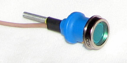
The photodiode used to record the illuminance variations of the measured lamp
In the OliNo case an OSD50-E is used but it can be any other model, as normally the photodiodes are more than fast enough to record variations in illuminance far beyond the human visible frequency of max 100 Hz. Look at the datasheet’s value at risetime which gives an indication (1/(2x risetime) is an indicator for a maximum frequency of variation).
Scheme and functioning
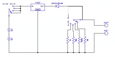
The photodiode is used in a way that it can easily measure big variations in illumination. A common scheme is to use the photodiode in reverse-bias such that the diode capacity gets smaller and that increases its bandwidth.
Use of the photodiode in reverse bias, and a series resitance over which the voltage variations are measured
In series with the photodiode is a resistor over which the voltage is measured. More light input results in higher current through the photodiode and hence more voltage over the resistor. When the resistor is selactable, one can select the amplification factor.
However the higher the resistance the slower the reaction speed; the diode has an internal capacitance (Cintern_max = 270 pF when reverse biased at 12 V) and this one is in series with the resistors. The value R*C gives an indication of the risetime (in some publications 2.2*R*C is assumed) and herewith an indication of the max reaction speed; the higher the series resistor, the higher the amplification and the smaller the bandwidth (the slower the reaction speed).
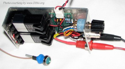
The measurement gear, with to the right the position switch and to the bottom left the photodiode, to the left the batteries and to the right the banana plugs. These are used to connect the voltage output to the data acquisition card
Measurements
The measurements are done by holding the photodiode close to the lamp in test. By selecting the correct series resistance a certain risetime results (approx 2.2*R*C, which corresponds to the max frequency of about 1/(3*risetime) ) and by assuring a minimal reverse voltage over the diode its linearity can be assured as well (with a certain reverse voltage the created charge carriers are pulled out of the iode area before they recombine, and with a minimal reverse voltage the capacitance is kept relatively constant as well). The voltage is measured with a data acquisition card that measured with 10 kS/s. So the signal that indicates the variations in illuminance should not have frequencies above 5 kHz.
During the measurement of the illuminance a max measurement voltage of 7 V is kept. This results in minimally 5 V for reverse voltage over the photodiode. In the datasheet one can read a resulting diode-junction-capacitance of 300 pH. With the resistances from the scheme given above the following results for the risetimes and the max frequency (both approximated):
| Rserie [Ohm] | Risetime [μs] | Frequencymaximal [Hz] |
|---|---|---|
| 1k | 0.7 | 500k |
| 10k | 7 | 50k |
| 100k | 70 | 5k |
| 1M | 700 | 500 |
In this table the effect of an additional capacitance coming from the connecting leads is not accounted for. So most likely the risetime will in reality be somewhat longer resulting in lower maximum frequencies than reported in the table.
The 100 k Ω resistance is a good choice that takes care that no frequencies exist in the resulting signal that are higher than the Nyquist frequency of the sampling speed of 10 kS/s of the data acquisition card. The maximum frequency of 5 kHz is far more than enough to identify variations in the illuminance at max 100 Hz that could be visible for the (trained) human eye.
Measurement values and measured parameters
Sampling speed is 10 kS/s during 1 second. The results are averaged over a period of 40 ms. The results are shown in a graph.
Measured illuminance variations with an incandescent light bulb
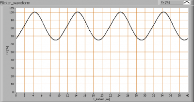
Herewith an example of the illuminance variations measured with an incandescent light bulb. The 100 % level is corresponding to a voltage of about 7 V (over the 100 k resistance). This result of max 7 V is obtained by playing a bit with the distance between the sensor and the light surface of the lamp that is measured.
From this data one can obtain a.o. the following interesting data:
flicker frequency fflicker =100 Hz, in other words theground frequency of the flickering effect is 100 Hz.
modulation index = 0.21 or 21 %, or the maximal amplitude of the variation is 21 % of the averaged value.
The illuminance modulation index is computed as: (EVmax – EVmin)/(EVmax + EVmin).
Measurement examples on lamps
In this chapter a number of lamps are measured and the results shown. This is a small selection. In the new lamp measurement articles a standard flicker measurement will be done and the results reported. So please look at the newest lamp measurement results.
1* this gives a so-called stroboscopic effect when waving one’s hand in this light.
Remarkable is the 20 % modulation index that is seen with ordinary incandescent lamps that apparently is not an issue for the human perception.
What can be an issue with regards to flickering effect are those lamps exhibiting a modulation index of at least 0.4.
Ledlamps can be constructed such that they show (almost) no variation at all in the illuminance.
GU53 lamps on DC do not show illuminance variation, which was expected.
Stroboscopic effect
The flickering of lamps results in a so called stroboscopic effect. By making photos of a moving object (here a hand) when a shutter speed of 1/10 sec is used (this is 10x longer than a ground harmonic frequency of 100 Hz) it is possible to see clear differences in stroboscopic effect between lamps; flickering lamps result in an image that has recognizable repeats of the hand (fingers. ring etc) in the photo. As soon as the lamp does not flocker, then a smooth blur results and not recognizable repeats of the object.
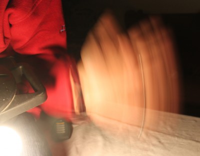
No stroboscopic effect, illuminance modulation index 0.0. The ring is one long line in the image.

No stroboscopic effect, illuminance modulation index 0.0. The ring is one long line in the image.
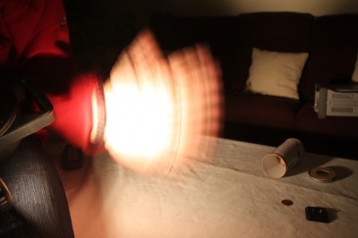
Stroboscopic effect, illuminance modulation index is 0.55
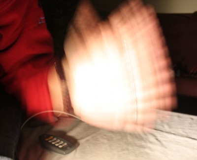
Strong stroboscopic effect, illuminance modulation index is 0.99
If one is working in an enviroment where is it of vital importance whether a part is moving or not (or rotating or not) then the choice of a lamp should be the one with low (<<40 %) modulation index value.



6 replies on “The flickering of light bulbs”
I’m thankful for your cool post… I will be subscribing
This is a brilliant website. I am planning the lighting in my kitchen so the info is really useful especially the luminance and dimmability data. Thank you. If there is one suggestion I could make, it would be to allow users to specific and select multiple lamps to be shown on the same chart so that comparisons are possible. Thank you…!!!
Dear kkc,
we are implementing more functionality on what you ask for. It will be easy then for anyone to choose the characteristics and get the results of the lamps that fulfill them. We hope to have the first implementation ready before Summer, on our Dutch website and then will port that to our other languages.
Hi,
is this available like product to buy and used it?
regards,
Ashok.
Dear Ashok,
Soon I will have three more, and then I am able to sell two of them. The costs will be 300 euro each.
There is also a measurement device that is hand held, and you can find it here: Lichtmeter LM 10.
Hi,
if you are interested and if you don’t mind German, please look on the way of measuring light flicker on my web site. Especially the 500 tested illuminants may be interesting.
I’d be glad for any response.
Thank you