 With the ledlamps becoming more and more powerful and given that the blue content of the light from leds in increasing as well, there is a growing concern for blue light hazard.
The IEC 62471:2006 norm explains about how to measure Blue Light Hazard, tha could lead to photoretenitis. This norm has an update in 2008. That update refers to the European Directive 2006/25/EC that contains the ELs. This article explains the way OliNo deals with this norm to measure the blue light hazard (only as an indication!) of the lamps it measures.
Update 28 April 2012: the dimensions of the brightest part of the illuminated part are taken for the calculation (of interest only in non-homogeneous sources).
Blue Light Damage
“Photoretinitis” or also “blue-light retinal injury”. The chance to get this damage is called “blue light hazard” (BLH). It is a photochemical damage to the retina. Photochemical means that due to the high energy content of the incoming light some chemical reactions take place on the retina. Blue light is the part of the spectrum with the highest energy content and that still can reach the retina (UV has even more energy but does not reach the retina as it is absorbed by the lens).
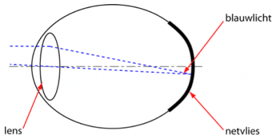
Drawing of the eye with the lens, retina and blue light that reaches the retina (blauwlicht is blue light, and netvlies is retina)
The area of the spectrum of the visible light that needs to be observed for the BLH is going from 300 nm (light UV, deep blue) to 700 nm (deep red). The most important part of this area is the sub-area between 400 – 500 nm. The peak of the sensitivity is around 440 nm.
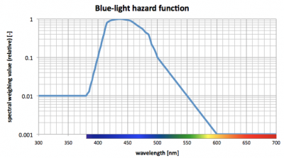
Relative sensitivity of the retina for the BLH; also other colors than blue take part!
Note: with ledlamps normally there is no energy content in the spectrum below 380 nm.
The damage-threshold levels of monkeys are well known; but the ones for human beings is hardly known. Only some data of people that by accident were looking too long in the direct sunlight could be used.
The BLH mechanism overrules the thermal damage when one observes long exposure times (more than 10 sec). Any disadvantageous effect is observable after 12 hours; at higher overdoses earlier. Some recovery is possible looked at the experiences with people looking too long in direct sunlight or arcs (when welding).
The symptoms are a blind spot on the retina that was hit with the light of the sun or from arcs. This is a loss of sight.
Experiences sofar with lamps is that it either occurs very seldom or that there is no reporting about it; the natural reaction to not look in direct sunlight probably is enough to prevent the BLH. Of course it can be that oversensitive people do get a harm due to BLH at values lower than the in the norm defined tolerable threshold values.
This is a very important issue: the information in this article comes from the norm that is mentioned before, and this norm states that it is valid for the majority of the people. But there are people more sensitive for whom these limits that are defined can be too high.
Exposure limit
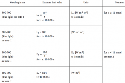
The exposure limit (EL) is found in the European Directive. It states that the employer shall prevent BLH to occur. The following ELs are given:
Note 1:
The range of 300 to 700 nm covers parts of UVB, all UVA and most of visible radiation; however, the associated hazard is commonly referred to as ‘blue light’ hazard. Blue light strictly speaking covers only the range of approximately 400 to 490 nm.
Note 2:
For steady fixation of very small sources with an angular subtense < 11 mrad, LB can be converted to EB. This normally applies only for ophthalmic instruments or a stabilized eye during anaesthesia. The maximum ‘stare time’ is found by: tmax = 100/EB with EB expressed in W m-2. Due to eye movements during normal visual tasks this does not exceed 100 s.
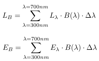
With:
LB = effective radiance (blue light): calculated radiance spectrally weighted by B (λ), expressed in watts per square metre per steradian [W m-2 sr–1];
EB = effective irradiance (blue light): calculated irradiance spectrally weighted by B (λ) expressed in watts per square metre [W m-2];
α = angular subtense: the angle subtended by an apparent source, as viewed at a point in space, expressed in milliradians (mrad). Apparent source is the real or virtual object that forms the smallest possible retinal image.
And:
B(λ) = spectral weighting taking into account the wavelength dependence of the photochemical injury caused to the eye by blue light radiation
Note with B(λ), see the graph presented earlier indicating the relative sensitivity of the retina.
A number of items are of importance to consider before OliNo could continue the measurements and calculations according the the mentioned equations. The IEC norm gives a lot of explanation about the measurement aspects and some of these important aspect are covered in the following chapters. Also is indicated the assumptions OliNo makes to make relevant measurements and calculations of the BLH of the lamps/luminaires it measures.
Size of the angle a of the apparent source
Depending of the size of the angle a of the apparent source the measurments need to be irradiance measurements E [W/m2] (αsource < 0.011 rad) or radiance L [W/m2/sr] (αsource ≥ 0.011 rad).
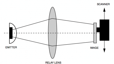
The angle α is related to the apparent source size. Apparent means that what is seen by the human eye. For instance a LED, which uses an integrated lens,the the apparent source size is not the physical size of the lens or housing. To find out the apparent source size one can use a measurement setup with in the middle a lens, with on one side the source (at twice the fical distance from the lens) and at the other side a screen (also at twice the focal distance). One image is projected on the screen of the size of the apparent source. With a camera behind the screen one can scan the image and find the apparent source size by taking 63.2 % of the area of light (sometimes one searches for 50 % light to dark transitions, meaning the 50 % value of the value measured in the middle of the image).
Setup to determine the apparent source size. Image taken from Agilent Application Note 1118.
In OliNo’s case not the leds are measured by whole luminaires containing one or more led(modules), lenses, reflectors etc. Then the apparent source size is equivalent to the dimensions of the area that emits the light (it can be the reflector size or a circle around the group of leds on a PCB or the dimensions of an opal cover etc). We do not worry about the difference between apparent source size and actual measurable luminous dimensions because:
– the lamp conists of more leds or led modules with space between the single leds. In this case when one led might have an apparent source size a bit bigger or different to its own physical size, it will make not a significant difference for the total area that all leds occupy.
– the lamp can have an opal or matt white cover, and then the physical dimensions of the cover are the (apparent) souce size.
OliNo will use the physical dimensions of the luminous emitting part of the lamp; in the C0-C180 direction which is taken as length direction, and in the C90-C270 direction which is taken as width direction.
If OliNo deals with a single led or with a lamp with a big lens covering one or a few led chips then it will estimate the apparent source size by looking at the size with the naked eye (when not switched on).
Update: April 28, 2012: if in a given case, the brightest area of a lamp is much smaller than the above-mentioned physical dimensions then not the physical dimensions of the lamp are taken but instead the dimensions of the brightest area. For example, a lamp in which a large reflector of average quality is positioned around the light source, then the light source itself is much brighter than the dimensions of the reflector. In this case, the dimensions of the light source are taken (which are smaller).
Maximum size of the angle α of the apparent source
There exists a maximum viewing angle (of 0.1 rad) for the eye to look at a source; when looking at light sources which luminous dimensions are extending an angle bigger than 0.1 rad then only that part of 0.1 rad is considered. Since large luminous areas divide their light energy over different parts of the retina. In the determination of the exposure limit these parts of the lamp outside the 0.1 rad give their energy on areas of the retina too far away from each other such that these energies do not add to the damage of one specific retina area.
OliNo measures a lot of light sources. Very often these are led-TLs. It is sifficient to tape part of these led-TLs since only maximally a viewing angle of 0.1 rad is relevant. Is the viewing angle larger than 0.1 rad then only 0.1 rad needs to be considered.
This is valid for both the C0-C180 direction as well as the C90-C270 direction.
Measurements with the irradiance E instead of the radiance L
OliNo measures irradiances E. The measurement sensor is positioned at a certain distance from the lamp and then starts to measure E(λ) [W m-2 nm-1]. This can be calculated into radiance L (for those cases where αsource ≥ 0.011 rad) by using a certain conversion factor (see also the IEC norm mentioned):
The α_average of the apparent source
The average value αavg of αsource is used. The IEC norm states the following:
As can be seen in none of the directions the value can be bigger than 0.1 rad.
OliNo uses this computation.
Maximum irradiance value of the source
The norm states that the maximum value should be looked for. This could mean a different viwing angle than straight underneath the lamp. For instance with energy saving lamps that have dimensions where the height of the luminous part is larger than its width.
OliNo measures straight underneath the lamp and then computes the exposure value. With the light distribution graph that it also measures one can compute the linear scaling factor when the maximum value is not straight underneath but in a certain direction.
Update 25 April 2013: for Ev only this is a linear adaptation. However to determin the exposure value and the corresponding group in which the lamp falls one has to recompute the alpha of the apparent source and then determine the exposure value again. If this is needed to be done for different viewing angles other than straight underneath the lamp then this can be done on request.
Lamp classification: report values at a distance where Ev = 500 lux
The IEC norm explains that for lamp classification it uses the measurement distance where Ev = 500 lux (for general service lamps). It states: “for lamps intended for general lighting service (GLS), see definition 3.11, the hazard values shall be reported as either irradiance or radiance values at a distance which produces an illuminance of 500 lux, but not at a distance less than 200 mm;“).
The decision to measure at a distance of 500 lux means that depending on the brightness of the lamp the measurement distance will be adapted. Lamps that are bright are then measured at a longer distance and hence the apparent source angle will decrease which results in a higher exposure value.
OliNo does not measure atomatically at a distance where Ev = 500 lux. OliNo measures at a distance of about 1000 – 1600 mm and always measures in the far field. Sometimes for big lamps part of the lamp then needs to be taped.
So OliNo needs to compute the results at a distance where Ev = 500 lux. If this distance is still in the far field of the lamp then the results are correct. If this distance is no nearby the lamp that it is in the near field of it, then the results are more than worst case. However a lamp that is so bright that it eventually could pose a blue light hazard will be so bright that the measuring distance where 500 lux is found is in the far field.
Irradiance measurements with a sensor with 7 mm diameter
The IEC norm talks about the iris opening of 7 mm when sources are used that have a high brightness. The sensor of the SpecBos 1211 that is used for these measurements has such a small sensor. A measurement device with a big sensor would give wrong values when measuring sources with very narrow beams.
In the measurement case of OliNo the minimal measurement distance is 1000 mm and as the opening of the sensor is 7 mm, then this corresponds to a openings-angle of 0.007 rad. Lamps with a beam angle this low has sofar never been measured by OliNo.
Computations and way of presentation of results
Measurements to determine the blue liht hazard are done straight underneath the lamp, then the irradiance E (λ) [W/m2/nm] is measured. When doing the measurement the following is known:
Llum0: dimension brightest lumious part of lamp in C0-C180 direction.
Llum90: dimension brightest lumious part of lamp in C90-C270 direction.
SSDmeas: Measurement distance from the surface of the luminous area until the surface of the measurement sensor.
Irradiance values of the spectrum E0@SSDmeas (λ)[W/m2/nm] straight underneath the lamp (valid at measurement distance SSDmeas).
And after analysis of many measurement data we also have available:
IV0 [Cd]: the brightness straight underneath the lamp.
MF [-] = a multiplication factor in case the lamp was partly taped during the measurement; lamps with big dimensions of luminous area are taped (during the light distribution measurement, not during the lumen measurement) to ensure that at the distance of about 1500 we are measuring in the far field.
Daarna volgen de berekeningen om te komen tot de bepaling van de blauwlichtschade blootstelling.
Then what follows are the computations to find the blue light exposure value.
First the computation of the distance where Ev=500 lux. Since IV0 [Cd] is known, we determine EV0@1m [lx] = IV0 [Cd] and:
![]() . We can check immediately whether at this calculated SSD500lx we are still in the far field of the lamp, by checking the following:
. We can check immediately whether at this calculated SSD500lx we are still in the far field of the lamp, by checking the following:
 . If this is the case then the next calculations are accurate. If this is not the case then we are more or less in the near field and then the computed SSD500lx is too big; one should measure nearer at the lamp to measure these 500 lux. A (slightly) too large SSD500lx leads to smaller source angles and hence exposure values that are too high. Hence we compute values that are more than worst case and so safe values. However, with a lamp that really has the potential to generate blue light hazard must be so bright that 500 lux will be consequently in the far field of the lamp.
Note that the norm also mentiones a minimum distance of 200 mm. If at 200 mm still the illuminance of 500 lx is not met then most likely the lamp cannot provoke a blue light damage. In any case, OliNo will then compute the values at 200 mm. This then means that for the following equations instead of SSD500lx we use a distance of 200 mm.
The computations of the (apparent source size) is what follows:
![]() .
.
We need to compute the average apparent source angle and need to assure that in both directions the angle is maximized at 0.1 rad:
The spectral values E0@SSDmeas (λ)[W/m2/nm] need to be adapted for various reasons; to the eventual limiting of angle to 0.1 rad, to the new distance SSD500lx and to the correction if the lamp was taped during the light distribution measurement:
When αavg ≥ 0.011 rad the following calculation is done to determine the exposure value (with radiance values, unit W/m2/sr):
however when αavg < 0.011 rad the following calculation is done (with irradiance values, unit W/m2):
Results in graphs
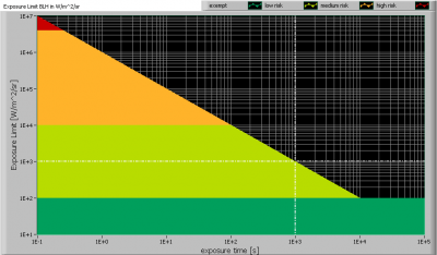
The found exposure value of radiance LB is shown as a horizontal line in the following graph:
Graph with Exposure Value for the radiance measurement result (LB). This example shows EV = 1000 W/m2/sr ingetekend.
The image shows in what area the light brightness is positioned, in this case the “low risk” area.
There are 4 distinct areas, see also the lamp classification for blue light hazard below.
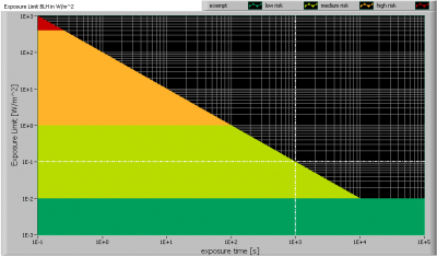
When the exposure value result has been calculated in irradiance values (when αavg ≥ 0.011 rad) then this value is shown in the graph below:
Graph with Exposure Value for the irradiance measurement result (EB). This example shows EV = 0.1 W/m2.
There are 4 distinct areas, see also the lamp classification for blue light hazard below.
Blue Light Hazard classification of the lamp
The IEC norm mentions a classification for the light of the lamp. This classification contains more aspects than only the blue light hazard, for instance infrared hazards. However OliNo only reports the blue light hazard classification.
The following groups are defined:
The lamp belongs to the exempt group when there is no bue light hazard within 10.000 sec.
The lamp belongs to the low risk group / group 1 when there is no bue light hazard within 100 sec.
The lamp belongs to the moderate risk group / group 2 when there is no bue light hazard within 0.25 sec.
Otherwise the lamp belongs to the high risk group / group 3.
Note that monochromators are recommended/requested by the norm to measure the blue light hazard. Olino measures with a spectrometer which is less accurate. Therefore consider the BLH EV as a good indication.



2 replies on “Blue light hazard for the human eye”
Dear Mr/Mrs
We were wondering whether you can help us with calculation the maximum irradiance strength we can have for our eye vision training device according to the IEC 62471-2008 standard. We are shining red and IR light around the eyes and we do not seem to understand the calculations used in the standard. Would you be able to help us with these calculations or provide us example calculations so we can follow the calculation process step by step? The calculations that are applicable to your situation are described in chapter 4.3.
We are planning to use 660nm and 880nm for our product and are looking for the maximum mW/cm2 strength that is allowed to shine on the cornea and retina of the eye during a treatment time of 180s.
I am looking forward to your reply.
With Kind Regards,
Bas van Hoek
Mechanical Engineer
The human eye is being exposed to blue light that is harmful to it. Think about the cataract, macular degeneration, or any other major illnesses caused by this particular hazard. It always follows that people should have blue light protection screen at the least.