Background THD and IEC-61000-3-2:2006 results in lamp measurement articles
Posted by Marcel van der Steen in Explanation 2 Comments» This article gives the background and explanation of the THD and compliancy to IEC-61000-3-2:2006 measurement details and results given in the lamp measurement articles.
From lamp measurement articles links will be used to refer to this explanatory article, and herewith keeping the measurement articles small in length and to-the-point, by preventing the same explanation over and over.
Harmonic distortion and conformity to IEC 61000-3-2:2006
Current- and voltage waveform
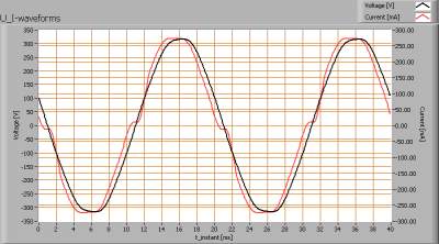
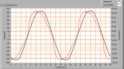
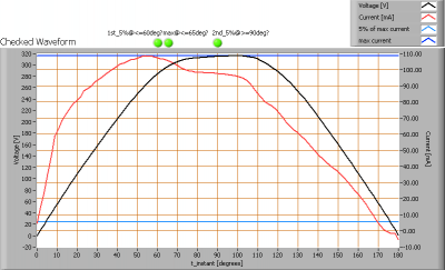
OliNo measures the voltage waveform across and current waveform through the lamps. It visualizes the result in an image.
The voltage across and current through a 50 W halogen lamp with transformer
The voltage across and current through a 17.5 W led-TL tube
The image of the waveforms shows how well the voltage as well as the current waveform is like a sine. If the current waveform is not a nice sine, then this indicates the presence of higher harmonics. This means that the total current can be thought of as a sum of a ground harmonic (a sine with its own phase and amplitude and a frequency of 50 Hz) and higher harmonics (each a sine waveform with own phase and amplitude and frequency being a multiple of 50 Hz); a harmonic is a sine waveform with a certain phase and amplitude and frequency (the latter being a multiple of 50 Hz in Europe). Also visible are eventually present steep edges that indicate presence of higher harmonics. The steeper, the more higher harmonics.
The harmonic content
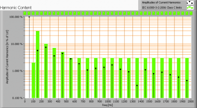
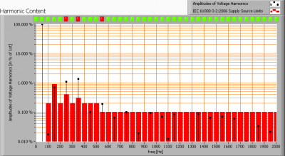
Harmonic content of the current through the 50W halogene + transformer
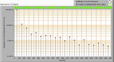
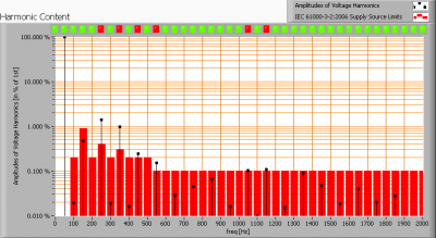
Harmonic content of the current through the 17.5 W led tube
The images directly above show the harmonic content of the current through the lamps (including their ballasts). The black bars indicate the amplitudes of the harmonics of the indicates frequency on the x-axis. One harmonic is indicated by (1) its amplitude by the height of the bar and relative in % to the 1st harmonic (50 Hz in Europe), and (2) its frequency indicates by the x-axis.
The sum of all these harmonics will lead to the waveform as indicated by the first image sin this chapter.
These images also show what a norm allows. The norm used here is the NEN-EN IEC 61000-3-2:2006 (plus amendments 1 and 2) that indicates the maximum values for harmonics for lighting equipment (class C in the norm). In amendment 2:2009 is decided that there are two specific limts for lighting equipment with consumed power > 25 W and <= 25 W. This is visible in the images.
The allowed harmonic content for the 17.5 W led tube is different than for the 50 W halogene light. The first has NO limits defined (note that only for gas discharge lamps <= 25 W there are limits for the 3rd and 5th harmonics. For these lamps with consumed power <= 25 W there is also a specific requirement for the current waveform, which will be explained later).
Both lamps that were taken as an example in this chapter fulfill the norm requirements; the black bars fall within the limits indicated by the wider green bars. There are led-indicators above each harmonic indicating whether each complies; they are all green. Green here means (1) the concerned harmonic complies, or (2) there is no limit in the norm mentioned (which is the case for led lamps with power <= 25 W).
Waveform requirement for gas discharge lamps within the lighting equipment <= 25 W
The NEN-EN-IEC 61000-3-2:2006/A2:2009 (this is amendment 2 from 2009) defines an additional set of requirements for the current waveform.
Check on the current waveform through the an imaginary gas discharge lamp
The additional requirements are:
- the actual value of the current reaches 5 % of the max valuelatest at 60º
- the actual value of the current reaches its maximum latest at 65º
- the actual value of the current is decreased to 5 % of its maximum value not before 90º
Indicators above the waveform image indicate whether each requirement is fulfilled (green = yes, red = no).
Requirement to the voltage waveform
There is also a requirement to the voltage waveform, of the voltage used to put across the lamp. These requirements pose (amonst others) limits to harmonic content of the voltage waveform.
Harmonic content of the voltage waveform across the 50 W halogene lamp
Harmonic content of the voltage waveform across the 17.5 W led tube light
The harmonic content of the voltage waveform applied across the lamps does not fulfill the harmonic limits mentioned in NEN-EN-IEC 61000-3-2:2006. The images and the indicators above the graphs indicate at which harmonic frequencies the non compliance occurs. The harmonics are not far outside the allowable limits, however care should be taken that a non perfect voltage waveform will have its effect on the current waveform as well. The results of the current waveforms should therefore be used with care and as a (serious) indication.
Dimming
The norm also takes dimming in consideration. When a lamp is dim-able, then 5 dim-positions need to be tested and the worst-case results taken.
Total Harmonic Distortion
The total harmonic distortion has a lot in common with what is explained in the chapter about conformity to IEC 61000-3-2:2006. This chapter explained about the concept of harmonics. The Total Harmonic Distortion indicates the total harmonic content of a current waveform.
Harmonic content has its consequences, as has been explained by the following from Bas van Duijnhoven:
Harmonics come a.o. from loads connected to the grid, and the consumer’s house. Harmonics can lead to problems in the installations upstream the consumer. These installations deliver the grid voltage and power to the consumer, and with more harmonic content the currents through the installations as well as the frequencies of the currents through it increases. This has a number of effects, also explained in the following publication of Schneider.
- Higher harmonics can generate electromagnetic fields influencing other equipment (called EMC). The allowable amount is specified in NEN-EN-IEC 61000-3-2
- Higher harmonics generate additional currents during the delivery of power to the (consumer’s) load. This results in additional heat induced in the cables, transformers, switches in the installations earlier mentioned
- Higher harmonics induce a higher voltage drop across cables since the X (the imaginary or inductive resistance) of a cable depends on the frequency of the current through it (the higher the frequency the higher eventually the X). Because of a skin effect the higher harmonic currents do only use the skin of the cable and less of the core, resulting in additional resistance increase and heat-loss and power loss
- In three phase systems the multiples of the 3rd harmonics generate a current in the 0-phase (there is no cancellation of these currents in the zero conductor but addition takes place). When the content of higher harmonics is higher this leads to high currents and possible overload in the 0-conductor. Many home installations have a single phase connection to the grid and do not recognize this problem, but for (small) companies it is a possible issue.
- 3 phase transformers: in the feeding part of the installation the transformers (of the utility company or a company’s own transformer) have a higher load because of these higher harmonics, requiring more over-dimensioning (and hence higher costs). Multiples of the 3rd harmonic are not present in the transformer (as the transformer filters these out, for the in The Netherlands often used transformer setup with a triangle-star setup)
- When generators are used to feed an installation with many harmonics then over dimensioning is needed to supply these harmonics as well. Utility companies require a minimum power factor for the loads of a campny, or otherwise require compensation.
Herewith a number of reasons why to limit higher harmonics. The loads used on the grid can be constructed such that harmonic currents are generated. The compensation can also be done in each and every load, ranging from passive power factor compensation to passive power factor compensation.
The computation of the THD, according to IEC 61000-3-2:2006
The THD is the ration between the r.m.s. value of the sum of the harmonic components (2nd – 40th harmonic, so from 100-2000 Hz so not including the ground harmonic of 50 Hz) and the r.m.s. value of the fundamental component (the ground harmonic, with 50 Hz).
The result that is given is given in %, so the value is multiplied by 100.



2 replies on “Background THD and IEC-61000-3-2:2006 results in lamp measurement articles”
Where is the THD measured–before the ballast or after (on HID)?
@ Kevin,
This article doesn’t talk about HID, but if I were to measure an HID then I would report the THD of the ballast + light source together. This is what is actually connected to the grid.