Giving background of BigMama’s light measurements
Posted by Marcel van der Steen in Explanation No Comments»This article explains some general items mentioned in the light bulb measurement articles. Hope they shed some light in the darkness.
Computation from illuminance E_v to luminous intensity I_v
When measuring illuminance E_v in lux at a certain distance from source to sensor, this illuminance E_v can be computed at other distances, as long as the measurement distance from source to sensor is at least about 5 – 10 times bigger than the maximum length of the source.
When the measurement distance increases a factor 2, then the illuminance decreases a factor 4. This holds as long as the source to sensor distance is much longer than the max length of the source.
Small source to sensor distances
Note: when the source to sensor distance is not much bigger than the max length of the source, there is a measurement error in determining the illuminance of the sensor.
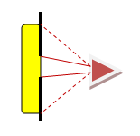
In yellow the source and in red a too near sensor, and in green a sensor at a better distance.
The sensor colored red is too near. This results in an illuminance value that is too low, for the following reasons:
- The light coming from the extremes of the light source enter the sensor at an angle that is far from the straight angle. The sensor is much less sensitive at light entering at angles (due to its cosine sensitivity) and hence the light will not be measured as strong as it should be.
- The light source itself most likely will output less light in an angled direction, so the light from its extremes in the given direction will be less than the light the extremes output at a straight angle.
- The distance from the extremes to the sensor is bigger than the distance from the center of the light source to the center. So the light of the extremes is (much) more attenuated.
The sensor colored green is farther away, and hence the mentioned effects will be much less. There is one drawback though; there is a lot less light available and hence the measurement will take considerably longer, or the measurement gets less accurate due to long measurement times.
Work around for a big max length of the light source
Note II: when the source to sensor distance is not much longer than the max length of the light source due to a relatively long max length of the light source, there is one way to work around it when the light source emits a constant intensity of light over its surface. One can then cover part of the light source and herewith decrease the max length of the light source. Cover as much as reasonably can be covered, such that the requirement of source to sensor distance is at least 5 times bigger than the max lenght of the light source is met.
Covering part of the source’s light emitting area and herewith reducing effectively its max length.
Determine accurately what part of the light source is covered. When for instance 75 % is covered, then one has to multiply the found illuminance data with a factor of 4. Since the light generated by the covered 75 % would be three times more than with the 25 % measured. And light is energy that simply adds up.
Addition April 2010: the fact that big lamps need to be partially covered, makes this way of working not acceptable for fluorescent tubes (meaning tubes working on the fluorescent principle, so not led tubes). Because covering the tubes results in heating up the tube to temperatures not comparable to those in normal application. This means that there is an impact on the tube current and hence light output when the tube is partially covered). It is possible to correct for this impact, by adding an other measurement. This additional measurement is as follows:
(1) the fluorescent tube longer than 60 cms are partially covered such that the length is approx 60 cm. Then the normal measurement procedure is done.
(2) after the measurement procedure, the tube is positioned in normal position (downwards lighting) and immediately the covering tape/sheets are removed. For one hour the illuminance [lx] is measured continuously.
(3) the change in illuminance [lx] indicates the correction that has to be made to the previously obtained illuminance [lx] values and also the lightflux [lm] value.
Normally OliNo prefers not to do this additional correction measurement, and proposes only to measure fluorescent tubes up to 60 cm. These tubes need not be partially covered. And at the end of the measurement procedure OliNo does also verify the change in illuminance when the fluorescent tube is positioned lighting downwards.
It is up to the customer to decide whether or not to have fluorescent tubes measured this way.
PS: led tubes are not sensitive to orientation. Sample tests done here according to this described methodology show differences in illuminance < 2 %.
Convert illuminance reading into luminous intensity
At 1 meter distance there is an equivalence in value between the illuminance and the luminous intensity. So when assuring at this distance that the source sensor distance is 5 – 10 times longer than the max length of the source that is measured, one can state:
Note: The illuminance is expressed in lux, which is lumen per square meter. The luminous intensity is expressed in Candela, which is lumen per ster radial. At a source sensor distance of 1 m, the ster radial is equivalent to an eara of 1 square meter. Hence the reason why these values are euqal.
Computation Luminous Intensity I_v to Luminous Flux Φ
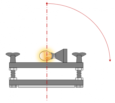
With BigMama a set of measurements is made in a half sphere around the lightbulb or lamp. The measurements start from right above the lamp at a 0 degree inclination angle, and then increase the inclination angle and for every inclination angle a number of measurements are performed at different turn angles.
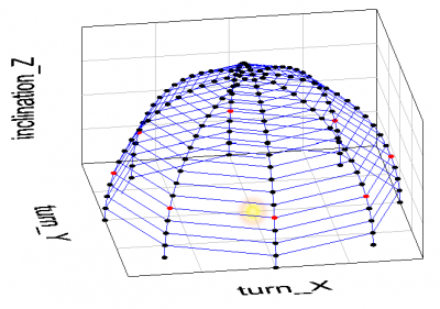
The measurements in red are at an inclination angle of 70 degrees.
The figure shows the measurements done at an inclination angle of 70 degrees, and at turn angles from 0 to 315 degrees with a 45 degree step. The light bulb is positioned where the yellow spark is shown.
At the dots the illuminance values E_v are measured, in lux which is lumen per square meter. If now the area is computed around the measurement dots, the luminous flux can be calculated.
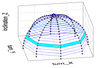
Area between 65-70 inclination angle.
The figure indicates the area between the 65 and 70 degree inclination angle. This area can be computed by first computing the area of the top of the globe at 70 degrees, and then subtracting the area of the top of the globe at 65 degrees inclination angle.
And where r (radius of the globe) is the source to sensor distance.
The illuminance value that is used for this area is simply the average of the illuminances of the dots that outline the area (so, in the picture the green and the red dots).
By now determining the area between all inclination angles and multiplying this with he averaged illuminance, and summing all the multiplications found, one gets the luminous flux.
Measuring/Computing flux of light bulbs emitting light all around
There are light bulbs that emit light not only in the top half sphere but also below. There are some ways that can be used to determine the amount of luminous intensity in the lower half sphere.
- put the light bulb on its side on the shelf that is mounted on the disk of the BigMama measurement tool. Then measure from above to below the light bulb. Extend the found values from the top half sphere with the measurement values found. If needed, then turn the light bulb and measure again. Make sure that the reflectance of the light against the disk on which it is mounted is neglectable.
Measuring in the bottom half sphere of the light bulb.
Note I: this is the OliNo preferred way.
Note II: to verify that the reflectance against the mounting shelf is neglectable, just cover the light bulb from above and only cover that part that directs light directly to the sensor. Leave the other parts uncovered such that these can reflect against the shelf and illuminate it. The sensor will then measure these parts. The illuminance value of the reflection alone should be neglectable (< 2 %) with respect to the total measured illuminance.
Verifying reflectance effect.
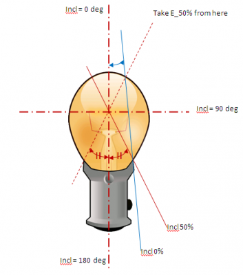
- determine the mechanical properties of the light bulb and compute the blocking effect of the light bulb’s base. Determine at what angles the intensity of light will be halved, and where it will be zero. Then linearize between these values in order to get the attenuation factors (expressed in percentage that is not blocked). After this use the averaged values of the top sphere and multiply these values with the attenuation values found; the angle at 100 degrees should use the illuminance value at 80 degrees multiplied by the attenuation factor belonging to 100 degrees. The angle at 150 degrees uses the illuminance value at 30 degress multiplied by the attenuation factor belonging to 150 degrees.
Computing the illuminance values in bottom half sphere.
The picture shows the lightspot in the light bulb which must be taken as a reference. In this example, an inclination angle at which 50 % of the light of the light spot is blocked can be determined, as well as an inclination angle where all light from the light bulb is blocked (however this inclination value is close to 180 degrees).
If the glass of this lighbulb would have been matte, then even at 180 deg there would be a little bit of light, albeit only a fraction. The trick is then to compute the area of the light bulb that is visible at an angle of 180 deg.
Illumination at 180 deg inclination.
Note that the computational way is not the preferred way of determining the light output of the light bulb.
Determining luminance values
For (professional) lighting application programs luminance values are asked as an input in order to be able to compute the distribution of light in a room. An other example is for deviation indicating purposes at highways, there are also minimum luminance requirements. This chapter explains how the Luminance values can be determined.
First of all, the luminance is expressed in Cd / m^2. The area which is mentioned is the effective light emitting area of the light source, and by dividing luminous intensity in Cd by the light source’s light emitting area, one gets an measure for the brightness of the light source.
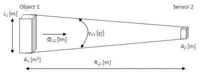
Assume there is a light object nr 1 and a sensor nr 2 capturing part of the light that object 1 emits.
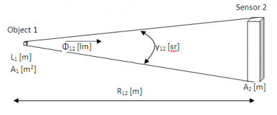
Setup and definitions to explain how to acquire the luminance L.
L_1: the max length that emits light, of source (object 1)
A_1: surface of source
Φ_12: luminous flux from source to sensor
γ_12: solid angle between source and sensor
R_12 is source to sensor distance
A_2: lights ensitive area of the sensor
If the sensor is far away from the source, the distance R_12 >> L_1 (a factor 5 – 10 bigger). In this case, the source can be seen as a point source which gives the following situation.
The sensor far away and the source seen as a point source.
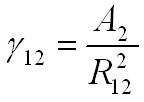
The solid angle γ_12 (in sr) can now easily be computed:
And also the luminous flux Φ_12:
Combining (VI) and (VII) gives:
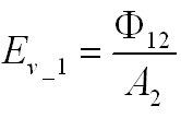
The sensor measures the illuminance E_v of the source (E_v_1), which can be related to the flux φ_12:
Interesting when combining (VIII) with (IX) gives:
where can be seen that the sensor’s area is of non importance! Which is understandable, as the luminance is constant, irrespective at what solid angle it is observed. So when A_2 would be bigger, it would mean a bigger solid angle (conform (VI)) so the sensor would capture more light (flux), but as it fills a bigger solid angle the luminance would remain the same.
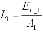
Finally the luminance of object 1, the source, can be computed with help of measurable values:
Equation (XI) holds as long as R_12 >> L_1. When measuring neared by, the R_12 will decrease but E_v_1 will increase with the inverse square of the distance, which results in that the luminance remains constant.
If the object 1 is so small that it can be measured from 1 m distance, the result becomes:
and:
which is the same as (II).
