 On a cold day, I was on the (non heated) attic of my house where the central heating pipes are running. When I touched the insulation around the pipes, I noticed they were feeling warm. This means despite the pipe insulation, warmth is escaping from the central heating pipes.
This article is based on the article Heat loss in pipe insulation on my website.
Measuring
I wanted to take some measurements to determine how much heat the central heating pipes were losing. I focus on the following two aspects :
- Heat loss via the insulation around the pipes.
- Heat loss via the pipe brackets, through which the pipes are mounted to the wall.
The Measuring Set-up
The components used for the measurements:
- A copper tube, 28 cm (11 inch) long and 22 mm (0.87 inch) diameter, the bottom side of the tube is sealed.
- A thermometer.
- Two resistors of 12 Ω (series connected) which I used as a heating element.
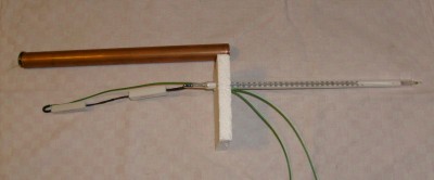
The Components for the Measurement
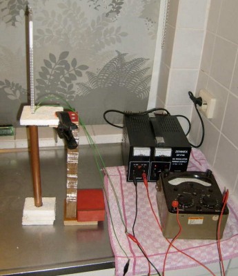
Set-up for Measurement 1
Description of the set-up:
- The resistors are put into the tube.
- The tube is filled to the edge with water, the thermometer measures the water temperature.
- The thermometer is put into the water through a piece of EPS (expanded polystyrene), which covers the top side of the tube.
- The bottom side of the tube is standing on a piece of EPS.
- For the rest, the tube is not insulated.
- The resistors are connected to a 10.0 Volt power supply.
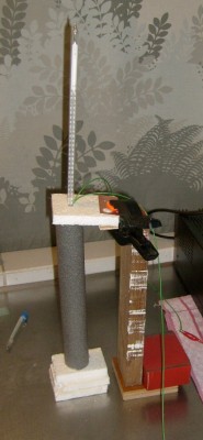
Setup for Measurement 2
Identical to set up 1, with the following difference:
- The tube is insulated with a piece of pipe insulation with 9 mm (0.35 inch) wall thickness
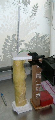
Setup for Measurement 3
Identical to set up 1 with the following difference:
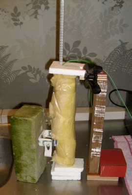
- The tube is insulated with 50 mm (2 inch) thick glass wool.
- After applying the glass wool, and winding tape around it, the glass wool was flattened to a thickness of 20 mm (0.8 inch).
Setup for Measurement 4
Identical to set up 1 with the following difference:
- A pipe bracket is attached to the tube.
- The pipe bracket is mounted on a brick.
- The tube insulation is the same glass wool insulation as in measurement 3.
Setup for Measurement 5
The set up for measurement 5 looks the same as the one for measurement 4, so also with glass wool insulation around the tube. Only in measurement 5 an insulating cloth is applied between the pipe bracket and the tube. The cloth can’t be seen, while it is covered by the glass wool. But on the picture below, you can see what I mean. I used a piece of a cleaning cloth with about 1.5 mm (0.06 inch) thickness.
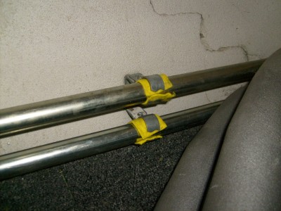
The cloth prevents direct heat transfer to the pipe brackets
The Measurement
Before starting the measurement, the temperature of the tube must be equal to ambient temperature. The water used for filling the tube must also be of ambient temperature. The starting temperature is noted, and the resistors connected to the power supply. The tube filled with water now will slowly warm up. At regular intervals, the water temperature is noted. One measurement can take some hours.
The Measurement Results
In the table below, the temperature difference between the water in the tube and the ambient temperature is shown. The temperature is measured with ± 0.5 ºC accuracy. If no value is noted, no measurement is done at that time.
| Tabel 1: Temperature increase of the tube (ºC) | |||||
|---|---|---|---|---|---|
| Time (minutes) | Measurement 1 Without isolation | Measurement 2 with 9 mm (0.35 inch) pipe isolation | Measurement 3 20 mm (0.8 inch) glass wool insulation | Measurement 4 20 mm (0.8 inch) glass wool insulation + non insulated pipe bracket | Measurement 5 20 mm (0.8 inch) glass wool insulation + insulated pipe bracket |
| 0 | 0 | 0 | 0 | 0 | 0 |
| 5 | 4 | 2.5 | |||
| 10 | 7.5 | 6 | 5 | 6 | |
| 15 | 10 | 8.5 | 8 | ||
| 20 | 12.5 | 11.5 | 10 | 11.5 | |
| 25 | 14 | 13 | |||
| 30 | 16 | 15 | |||
| 35 | 17.5 | 17.5 | 18.5 | ||
| 40 | 19 | 20.5 | |||
| 45 | 21 | 23 | |||
| 50 | 22 | 24 | |||
| 55 | 22 | 27.5 | |||
| 60 | 29 | 25 | 27.5 | ||
| 65 | 26.5 | ||||
| 70 | 24 | 27.5 | 30 | ||
| 75 | 34 | ||||
| 80 | 25 | 29.5 | 32.5 | ||
| 85 | 30 | ||||
| 90 | 31 | 38.5 | 31.5 | 35 | |
| 95 | 26 | ||||
| 100 | 32 | 37 | |||
| 105 | 42 | ||||
| 110 | 27 | 35 | 39 | ||
| 120 | 34 | 45 | 40.5 | ||
| 130 | 28 | 37 | 42 | ||
| 135 | 35 | 48 | |||
| 140 | 38 | ||||
| 150 | 28.5 | 36 | 50 | 38.5 | |
| 160 | 36.5 | 39 | 45 | ||
| 165 | 52 | ||||
| 170 | 39.5 | ||||
| 180 | 53 | 40 | |||
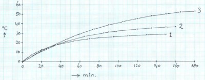
The values from the table shown in a graph.
Graph 1:
Warming up of the tube.
Line 1 = without insulation around the tube.
Line 2 = with 9 mm (0.35 inch) pipe insulation around the tube
Line 3 = with 20 mm (0.8 inch) glass wool insulation
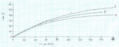
The effect of the pipe bracket
Graph 2:
Warming up of the tube.
Line 3 = with 20 mm (0.8 inch) glass wool insulation
Line 4 = with 20 mm (0.8 inch) glass wool insulation and non insulated pipe bracket
Line 5 = with 20 mm (0.8 inch) glass wool insulation and insulated pipe bracket
Formulas for calculating the heat loss
The power of the “heating element” is (10 volt)² / 24 Ω = 4.166 Watt, this power I call: Pin. One part of this power provides the warming up of the tube with water, by which the temperature of the tube increases, this part of the power I call: Pheat. An other part of the power will get lost by heat loss, this part I call: Ploss.
At the beginning of the measurement (t0 = time zero) the heat loss will be zero, because the tube has ambient temperature, all added power is then used for warming up the tube. What I want to know is the heat loss in Watt per ºC. For the heat loss applies:
Where:
Qloss is the heat loss
T1 is the measured temperature of the tube with regard to ambient temperature at point of time t1
or
Where:
∆T1 is the speed of the warming of the tube (in °C/minute) at point of time t1
∆T0 is the speed of the warming of the tube (in °C/minute) at point of time t0
Combining formula 2 and 3 gives:
Combining formula 1 and 4 gives:
Results of the Calculations
With formula 5 the heat loss of the measured setup is calculated.
| Table 2: Calculating the heat loss for the 5 measurements | ||||||
|---|---|---|---|---|---|---|
| Measurement | Pin Watt |
∆T0 ºC / W |
∆T1 ºC / W |
t1 minuten |
T1ºC | Loss W / ºC |
| 1 | 4.166 | 0.75 | 0.0375 | 130 | 28 | 0.1413 |
| 2 | 4.166 | 0.5666 | 0.0666 | 135 | 35 | 0.1050 |
| 3 | 4.166 | 0.6 | 0.1 | 165 | 52 | 0.0668 |
| 4 | 4.166 | 0.5 | 0.05 | 160 | 39 | 0.0961 |
| 5 | 4.166 | 0.6 | 0.1 | 145 | 43.5 | 0.0798 |
The tube length is 28 cm (11 inch), so the given losses are also per 28 cm (11 inch) tube. For measurement 1, 2 and 3 we can calculate the loss per meter tube, by dividing the results of table 2 by 0.28m. This gives the following results:
Measurement 1: loss is 0.5046 W / ºC.m with non insulated tube
Measurement 2: loss is 0.3750 W / ºC.m with pipe insulation 9 mm (0.35 inch)
Measurement 3: loss is 0.2386 W / ºC.m with glass wool insulation 20 mm (0.8 inch)
The difference in loss between measurement 4 and 3 is the loss caused by one non insulated pipe bracket,this is 0.0961 – 0.0668 = 0.0293 W / ºC
The difference in loss between measurement 5 and 3 is the loss caused by one insulated pipe bracket, this is 0.0798 – 0.0668 = 0.013 W / ºC
A Practical Example
The central heating pipes on the attic of my house have a length of 16 meter, so 16 meter flow pipe, and 16 meter return pipe. The flow pipe is 80 ºC (176 ºF). The return pipe is 50 ºC (122 ºF). The temperature on the attic is 10 ºC (50 ºF). So, the difference with ambient temperature is: 70 ºC (158 ºF) for the flow pipe, and 40 ºC (104 ºF) for the return pipe. By multiplying the heat loss in W / ºC.m by the pipe length and temperature difference, we get the energy loss of that pipe. The following table shows how much energy we lose with different kinds of insulation.
| Table 3: Energy loss with different kinds of insulation | |||||||
|---|---|---|---|---|---|---|---|
| Kind of insulation | Length flow pipe (m) | temp. difference flow pipe (ºC) | energy loss in flow pipe (W) | Length return pipe (m) | temp. difference return pipe (ºC) | Energy loss in return pipe (W) | Total energy loss (W) |
| No insulation | 16 | 70 | 565 | 16 | 40 | 323 | 888 |
| 9 mm pipe insulation | 16 | 70 | 420 | 16 | 40 | 240 | 660 |
| 20 mm glass wool | 16 | 70 | 267 | 16 | 40 | 153 | 420 |
Example of energy loss at 16 meter (52 feet) pipe length. We see, the loss can be reduced by hundreds of watt’s with a good insulation. Both flow and return pipe are on my attic fixed by 10 pipe brackets. The following table gives the energy losses in the pipe brackets.
| Table 4: Energy loss in the pipe brackets | ||||||||
|---|---|---|---|---|---|---|---|---|
| Kind of pipe bracket | Number of brackets | ∆Temp. flow pipe (ºC) | Energy loss per bracket in flow pipe (W) | Energy loss in 10 brackets in flow pipe (W) | ∆Temp. in return pipe (ºC) | Energy loss per bracket in return pipe (W) | Energy loss in 10 brackets in return pipe (W) | Total energy loss (W) |
| Non insulated | 10 | 70 | 2.05 | 20.5 | 40 | 1.17 | 11.7 | 32.2 |
| Insulated with 1.5 mm thick cloth | 10 | 70 | 0.91 | 9.1 | 40 | 0.52 | 5.2 | 14.3 |
Insulating the pipe brackets also gives a small saving.
Extra insulation
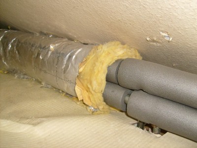
Below are some pictures of the insulation I applied in connection with the measurement results. I chose to keep the original pipe insulation intact, and applied an extra layer of glass wool around it. I removed the glass wool (with permission) from a house which was being demolished. It was free and as it also reduces waste, these are also kinds of savings.
If you choose, you can also apply an even thicker layer of insulation, and reduce the heat loss even more.
As we see, the pipe insulation wasn’t fully applied on all places. On other places, the pipe insulation was applied over the pipe brackets, but because of the extra thickness of the brackets this led to a chink in the insulation. By applying the extra glass wool insulation, these points are now also warmly packed.
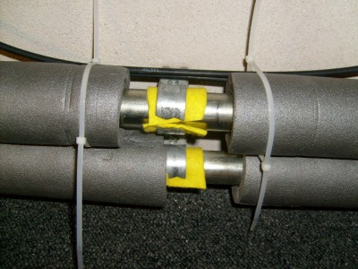
Insulating Cloth between Pipe and Pipe Bracket
The Saving
Let’s say we can reduce the heat loss by 250 watt through a better insulation. If the central heater is heating for 500 hours per year, this leads to a saving of 125 kWh. At an energy content of 8.8 kWh per m³ gas, and a heater efficiency of 85 % , the saving will be 16.7 m3 (590 ft3) gas per year. With an average natural gas price of $11.59 Mcf (Thousand cubic feet) this will save you 590 x 0.001 x $11.59 = $6.83 per year. In a period of 15 years, you will save $103. As soon as natural gas prices will rise, which is the expectation, your savings will increase more.



3 replies on “Heat Loss in Pipe Insulation”
This is the kind of result I love to read. 6.83$/year
This is the info you need to ask yourself if it is worth it or not.
Thank you. Great article.
Good Staff
My i get further technical support related to steam and thermal boiler and their piping insulation
Thanks
This is a nice information about pipe insulation. Thanks for sharing this article.