Power Factor, THD and current trough neutral line
Posted by Marcel van der Steen in Explanation 1 Comment» Suppose you want to change the current light bulbs into new ones, for instance led illumination. What does that mean for the current through the neutral line, harmonics etc? Recently I received three questions. An answer was so lengthy that it would not fit on the FAQ, hence a little article.
Questions
1. The cos φ remains the same when going from one luminary to 100?
2. What does the value of the harmonic content? This is with only one luminary comparably much less than with 100 luminaries?
3. What is the effect on currents through the neutral wire? How high will it be when using 100 luminaries?
Answers
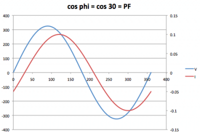
Ad 1: Correct, however one can better use Power Factor (PF) instead of using cos φ. This last only indicates the difference in phase. See the following example.

In this example the current has a nice sine form, and lags the voltage with 30 degrees. The cos φ = cos 30 = PF in this case.
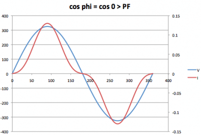
The next example shows a different result.

Now there is no phase difference between the current and the voltage, so cos φ = 1 (since φ = o degrees). However there are blind currents and higher harmonics! The current has not a nice sine form and herewith not equal to the voltage form and so sub-optimal to carry power over, as there is also a part of blind power. The PF accounts for this and will be < 1.
Considering the PF of one single luminary, and now putting 100 in parallel, it won’t affect the PF for the whole as it concerns all the same luminaries and every luminaire has the same PF.
Ad 2: the harmonics are added. However the relation between ground harmonic current and the higher harmonics stays the same even considering 1 or 100 luminaires.
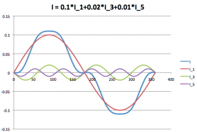
Take the following example. A light bulb has a current that can be thought of as the sum of three currents: the ground harmonic of 50 Hz with a certain amplitude, say 100 mA. Then a 3rd harmonic with amplitude 20 mA and the 5th being 10 mA.

The resulting current is I and has no sine form (when the voltage has a since form, then this results in a PF < 1).
When 100 luminaries are put next to each other (in parallel) the current I will be 100-fold. As the current I is the sum of its harmonics, each and every harmonic also is 100 times bigger when using 100 luminaries. In comparison this does not make any difference.
However not the following: when there are almost no harmonics in an existing installation (so a low Total Harmonic Distortion, THD) and a luminary is connected with a worse THD, then this luminary will not affect the system’s THD. More luminaries however will negatively affect the system’s THD and then one can conclude that using more luminaries can negatively affect total THD.
Ad 3: The effect on the currents through the neutral wire, is not easy to predict. This depends on different parameters:
- are all luminaires evenly distributed over the three phases? Assuming so, then all 3rd (and 6th, 9th, 12th, 15th etc) harmonics add in the neutral wire.
- The following spreadsheet gives the opportunity to play with this. The amount of higher harmonics can be input on tab 1 and then on tab 2 the results on the current trough the neutral wire can be observed.
- Pay attention that when the 3rd harmonic has an amplitude of 33 % of the ground harmonic, then the current through th neutral wire is as high as the current through the phase!
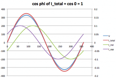
- It depends on which other users are attached the grid and hence make part of the observed system. Effects on blind power can become worse as well as better. An example given here shows and inductive and capacitive current, both equal amplitude. The phase shift is +30 and -30 degrees with the voltage. The effect of putting these two currents together results in a totl current without anye phase shift so PF = 1 (or at least increased).
In a system the neutral wire sometimes is thinner than the phase wires. This to safe costs. However a determination must be made whether thinner neutral wires are allowable by measuring the currents through these in an actual system.
If such a measurement has shown in the past that with a certain load distribution among the three phases the resulting current through the neutral wire is allowable, then care must be taken when changes to the loads and their actual distribution are done. Say the luminaries based on fluorescent tubes are changed for led tubes, one must again measure the currents through the neural wire when the old luminaries are changed for new.
The disadvantage of this measurement is that it is done after exchange of the luminaries. Comparison of the old and new luminaries on THD and especially 3rd, 6th, 9th etc harmonics, will also give an indication on what change can be expected on the currents through the neutral wire. OliNo gives the harmonic contents of luminaries and lamps measured by her.
The better the THD the better your chances for an improved result in your system. Please note that even a better THD does not mean the result is always better; it can even be that previously cancellation occurred and with improving the THD of the luminaries only the system THD can become worse.
Thanks to Bas van Duijnhoven for his contribution to this article.


1 reply on “Power Factor, THD and current trough neutral line”
We have a device that eliminates all harmonics and neutral line currents, and corrects power factor to unity all in real time and continuously.
Check out the website. It is fascinating. This begins a new era in energy management and distribution!