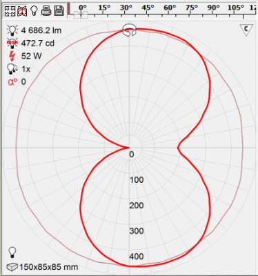
 With every lamp measurement comes an eulumdat file. This is a photometric file enabling you to simulate light distribution and light patterns in a certain area like an office, or on streets etc.
It appears that two programs, Qlumedit, and LDTeditor, do read in differently an equal eulumdat file when symmetry is present along the C90 C270 axis.
Personally, I do not understand the way LDT editor does it.
Update 3 March 2015: One more catch with DIalux and IES file. Dialux does not well understand dimensions used in IES files.
Tests and results
The test done was to generate eulumdat files of a streetlight. This streetlight has a symmetry along its C90C270 axis. Three eulumdat files were created, one without symmetry, one with symmetry along the C90-C270 axis and one with symmetry along the C0C180 axis (this latter just for comparison).
The attached document shows the results.
When taking the no symmetry file as a reference, then Qlumedit shows results for the C90C270 file and the C0C180 symmetry file that relate back to the no symmetry case. However LED editor seems to swap the interpretation of the turn angles C90 with C270 when it reads in an C90C270 symmetry file.
The reason why is unknown to me. A clarification has been asked for to Dial.
LDTeditor and Dialux
Note that Dialux has the same inconsistency as LDTeditor. So Dialux expects and .ldt file, with C90C270 symmetry, to have its C-plane axis swapped!
This means that, as most customers work with Dialux, they need to have this specific swap in C-planes otherwise the luminaires do not import well and the C90 and C270 planes are swapped. This is visible when importing a street luminaire and the C90 plane it towards its own pole, thereby illuminating its own pole.
This can be solved by swapping the C-plane axis, in the event C90C270 symmetry is used. OliNo will, by default, swap the C-planes in the event a luminaire with C90C270 symmetry is measured, in order to be compatible with Dialux. When opening such file in Qlumedit, then one can verify that the C90 and C270 planes are swapped.
Source files (ldt) and programs used
To be complete see here the eulumdat files used for this test (file without symmetry, file with symmetry along C90C270 axis and file with symmetry along C0C180 axis.
The programs Qlumedit and LDTeditor can be found on the web, for free.
Convention used for streetlights
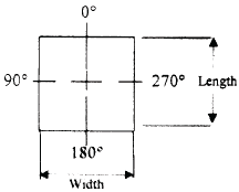
To be complete herewith a document explaining the convention used for streetlights, and where the C-planes should be. One can also see that European and US conventions are different…..
Dialux does not import IES files well: problem with dimensions of cylinder
IES files are well described how these are made (see for 95 version page 31 and further) and how these should be interpreted. Dialux seems not to understand this always well.
Example when the luminous dimensions of a light source are used defining a horizontal cylinder oriented along luminaire width.
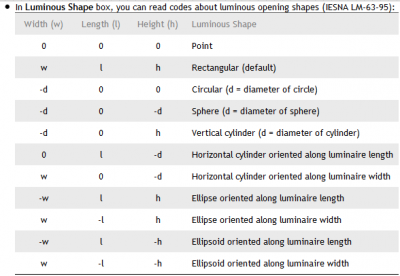
According to the IESNA LM-63-95 these are the options to define the luminous surface:
So to define the cylinder oriented along the luminaire width one should use w 0 -d.
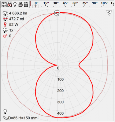
And when we do that and load the IES file in IESviewer.exe, we get the following result:
So you can see that a cylinder is defined with diameter 85 mm and length 150 mm, and the figure is somewhat horizontal (because in vertical case the cylinder would be really pdrawn vertically).
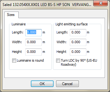
When loading this file into Dialux 4.12 then we get the following result:
Dialux does not recognize the dimensions of the light emitting surface and therefore it shows all zeros. This means it does not recognize the dimensions defined in the correct IES file definition.
My suggestion to make it work with Dialux, it not to use cylinders of ellipsoids in IES files. So instead of a cylinder of 85 mm one could better use the rectangle of 85 x 85 mm. See what happens:
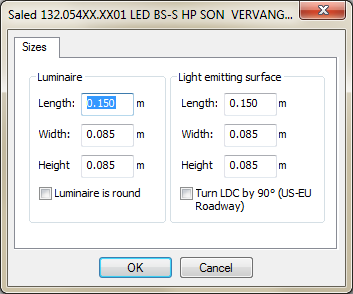
Now we see a box of 150 length (horizontal) and cross section is a square of 85×85 mm. And this is how it loads into Dialux:
Now Dialux does recognize the dimensions and shows them. And it asks you to define the luminaire dimensions so it can correctly draw the luminaire (as in the IES file there are no luminaire dimensions defined).
